+44 0208-800-3289


CAD

Computer Aided Design


Basic Engineering Drawing Concepts

Orthographic Projection

In engineering, communication between the drawing office and the workshop is achieved mainly by means of engineering drawings and the principal method used to prepare these drawings is known as Orthographic Projection. Basically, orthographic projection is the representation of a three-dimensional component on a flat surface (the drawing sheet) in two-dimensional form. At least two orthographic views are required to indicate fully the shape and size of a component. If the component is a complicated one more than two views are necessary to facilitate or aid understanding.

Orthographic projections are facilitated within traditional 3D CAD, surface modelling and solid modelling software. These now have very competent 3D modelling tools, so true orthographic drawings can be derived or captured from a solid model. One advantage of using traditional CAD software, over dedicated surface modelling or solid modelling software, is the flexibility in presentation afforded. Further advantage from CAD software is that orthographic projection or technical drawing derived from a solid model can be set up and dimensioned to drive changes to the 3D model if required

Detailed Drawings

A detail assembly drawing shows how all components are assembled and provides all the necessary details, dimensions and joining techniques (including welding) to fully assemble all or part of the project. It has several detailed drawings within it.

  • One or more of the components are drawn in more detail.
  • All the individual components have item numbers, i.e. Item 1, Item 2 etc.
  • The detail for these components is shown in the assembly drawing or in separate views, or on a separate detail drawing.
  • All the views necessary to gain a good understanding of the drawing are shown.
  • The measurements to manufacture the project are given


Solid Modelling

3D solid modelling is a critical aspect for modern product development and provides the basis for design, simulation, and manufacturing of any part and assembly across a broad range of industries, applications, and products. Solid modelling carries with it parametric data employed in both pre-production testing such as stress analysis and manufacturing processes such as CNC milling.

3D solid modelling speeds the creation of complex parts and large assemblies. Creating 3D solid models of your designs instead of 2D drawings has the following advantages:

  • Speeds design development and detailing
  • Improves visualization and communication
  • Eliminates design interference issues
  • Checks design functionality and performance (without the need for physical prototypes)
  • Automatically provides manufacturing with 3D solid models that are required when programming CNC machine tools and rapid prototyping equipment
A virtual 3D model of a machine, piece of equipment or even a production line may be designed from individual components. This allows dimensional tolerances to be precisely applied to a design pre-fabrication and the best third-party components selected. A discreet renderer enables the capture of high quality images for visualization purposes if required

Visualisation - Rendering

Photo-realistic 3D visualisation and 3D modelling transforms an idea or 2D design into an easy-to-understand, high-impact image that enables clients to view and understand their design in a more tangible way.
Mechanical services, architectural details or concept designs can be created in any varying measure of detail, from a basic clay type image to full photo-realistic detail with texture and depth. This cost-effective technology brings the design to life and greatly facilitates communications with clients and other design team members during the tender and design stages of a project.

Some of the benefits include:

  • Ability to understand and comment on the design without incurring actual material costs
  • Visualise the impact of the design in existing surroundings
  • Improved control of material and finishes selection
  • 3D Visualisations, Photo-realistic images, and Product visualisations enhances communication
  • 3D Walkthroughs, Flythroughs, and Product animations ideal for marketing product or service
  • 3D Interactive environments - move around your model with ease (Assists with complex decision making)
  • 3D Visual Impact Images and Visually Verified Images Essential for planning consultants
Retail, interior design and architectural visualization are catered for via non CAD 3D software. Here the emphasis tends to be on form and artistic preference.


Engineering Drawings

Like a picture, "an engineering drawing is worth over a million words". It is a communication language engineers, designers and technicians can not do without. To paraphrase it, virtually nothing can be produced or manufactured without them. Thus, it should come as no surprise that a lot of effort and money has been spent by multinational corporations to develop and design software applications to facilitate this endeavour ( Pro/ENGINEER, CATIA, Siemens NX, SolidWorks, Auto-cad to name but a few) .

The myriad of cad programs in the market today is testimony of the advantages attained in using electronic tools over manual drawing. If the advantages were to be enumerated here, you will probably still be reading it come tomorrow. Suffice to say a "Drawing Board and T-Square" in today's electronic world is akin to two courier businesses where, one uses bicycles (manual drafting) and the other (the cad user) utilising top BMW 850cc-motorbikes. No contest really. The above analogy slightly understated we hope illustrate the advantages of using CAD. However, if you are the bicycle courier with an aversion to motor-bike (pun intended) all is not lost. We are here to help you compete on a level playing field without incurring the overhead cost involve (software, hardware, human resources - the lot).

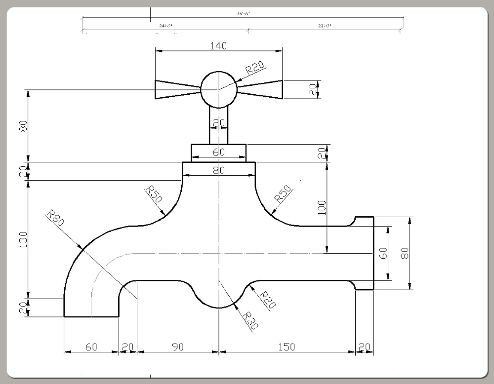
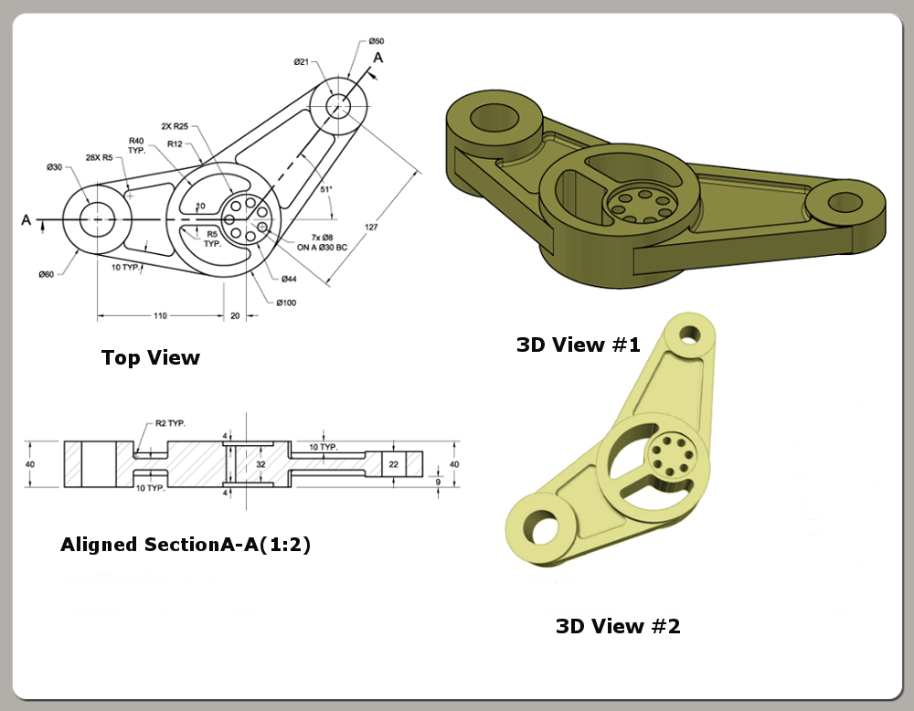
Cad systems in the main come in various flavour. Some are intended for general drawing work while others will focus on specific engineering applications. Thus, there are programs that enable you to do 2D drawings, 3D drawings, renderings, shadings, engineering calculations, space planning, structural design, piping layouts, plant design, project management etc.

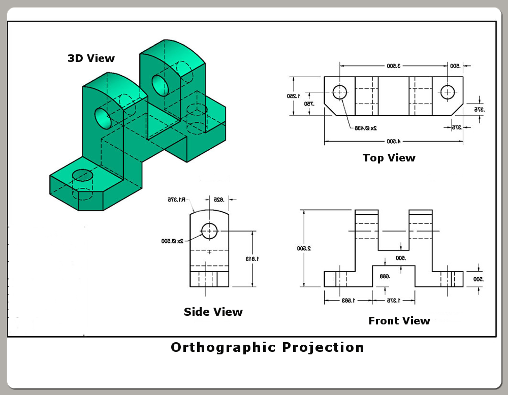
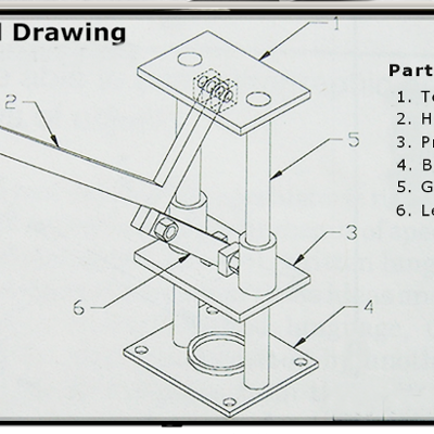
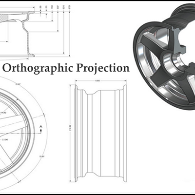
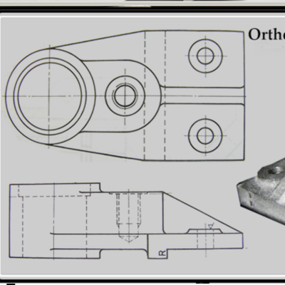
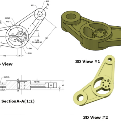
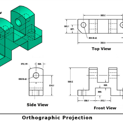
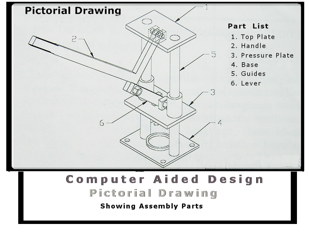
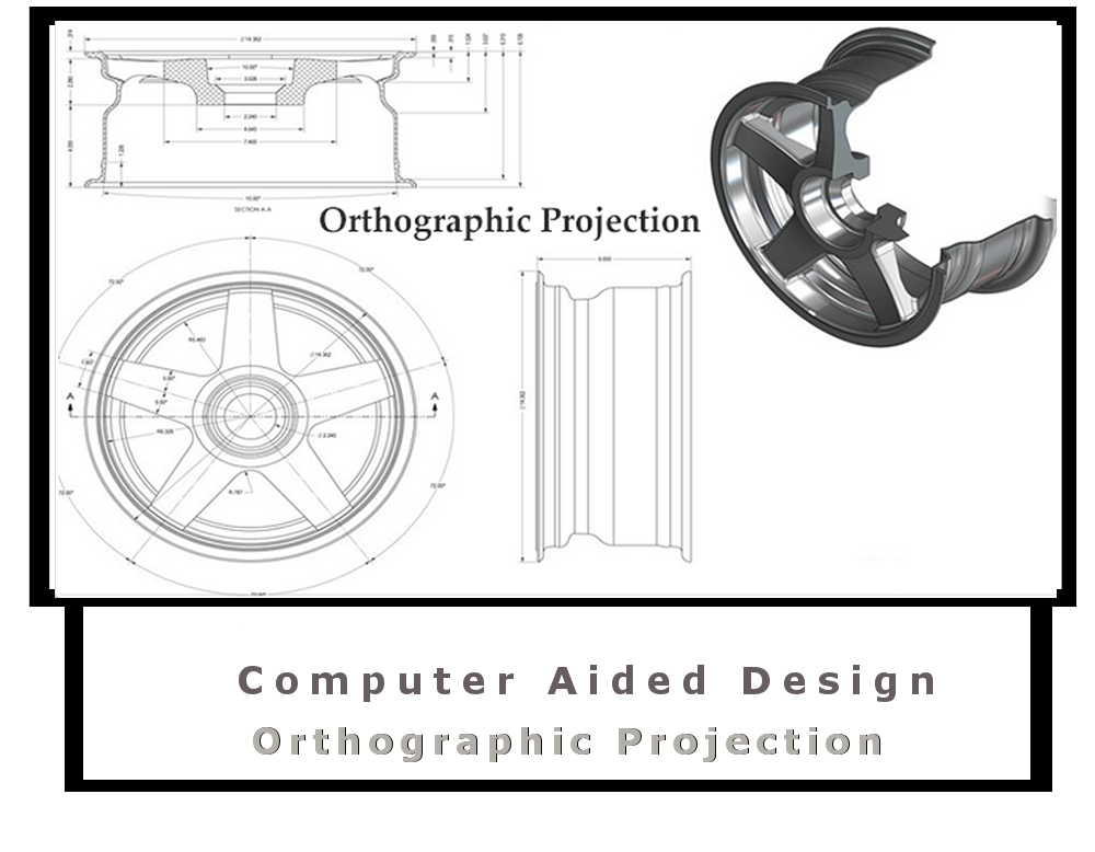
Today AutoCAD (a product of Auto-desk) is generally recognised as the industry standard cad application with the capability to fulfil every drawing needs. However, as most engineers and designers will attest, sophisticated software will never be a substitute for creativity and original ideas. We have considerable experience and expertise in using this application in both 2D and 3D environments respectively. Coupled with engineering expertise we are in a position to help you concentrate on your core business while we handle all your drawing needs. This in general, will range from orthographic, isometric, detailed and assembly drawings to 3D models. Specialized and bespoke drawing services are also undertaken (i.e."reverse engineering" and the transfer of hard copy drawings to electronic format). Our CAD operators are experienced in the latest Auto-desk products to provide quality services and support.

Our Services In CAD

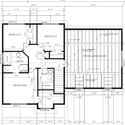
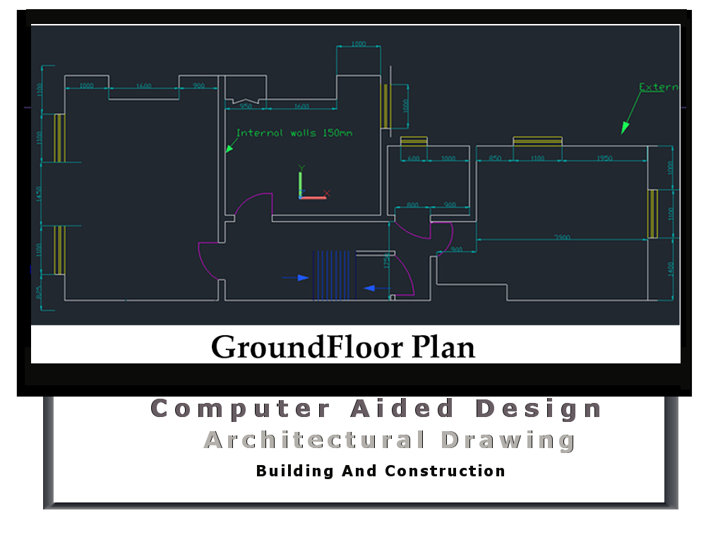
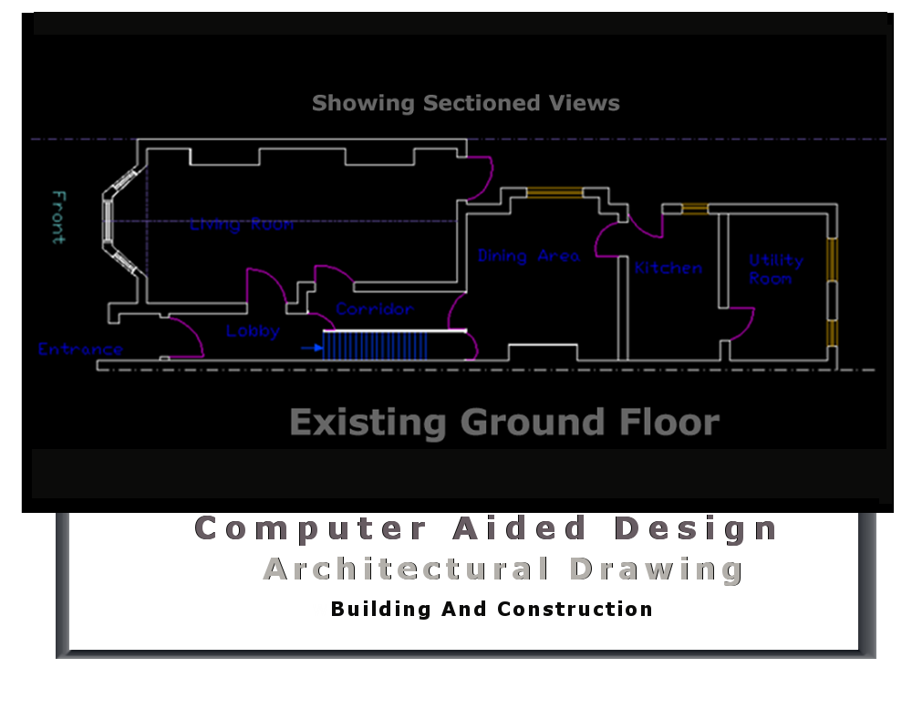
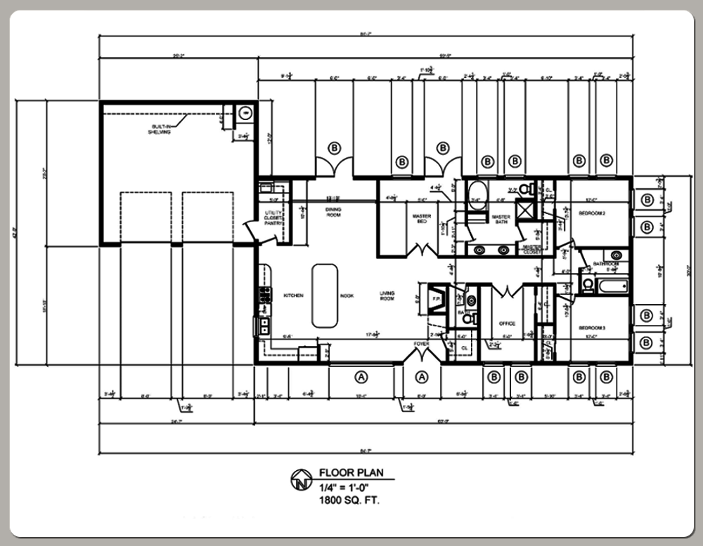
Mechanical - Architectural - Electrical

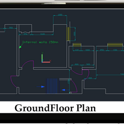
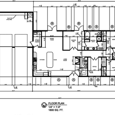
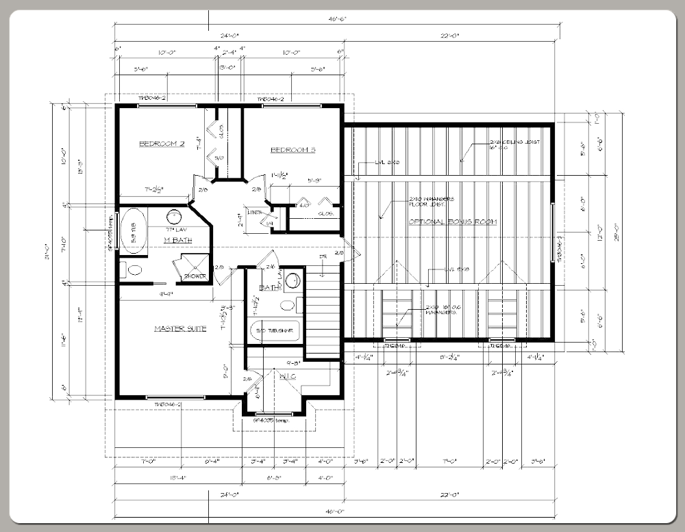
We used Auto-cad extensively for Mechanical, Architectural (building construction) and Electrical Engineering projects respectively. We are conversant with all the ISO related standards. Thus if you are a small or medium size enterprise in any of the above professions, we can be a far more cost effective solution to look at. While you concentrate on your core deliverables we can handle the technical drawing aspect of your projects. Especially in situations were the aforementioned need to be verified by an authorised body - local authorities or a professional body.

View More Technical Drawing